Portsmouth sits on a peninsula with an average elevation barely 8 metres above sea level, and that low-lying topography combined with 4.5 km of waterfront means retaining structures here deal with groundwater from day one. We have designed walls across the city—from the London Clay slopes near Portsdown Hill to the made-ground fill behind Gunwharf Quays—and the single biggest variable is always the depth to the chalk bedrock. Where the chalk is shallow, a gravity wall keyed into Grade III chalk can be straightforward; where the clay runs deep beneath former marshland, we rely on embedded cantilever walls with careful drainage detailing. The slope stability analysis often runs in parallel because many Portsmouth sites sit on the edge of existing cuttings or re-profiled ground left from nineteenth-century fortification works.
In Portsmouth, the difference between a wall that lasts and one that moves is knowing exactly where the chalk begins—and designing the drainage before you design the reinforcement.
Process overview
Local context
Portsmouth’s urban fabric expanded rapidly after the 1840s when the railway arrived and the dockyard drove housing onto former marshland and reclaimed creeks. That legacy means many retaining wall projects today sit on made ground that was never engineered to modern standards—we regularly encounter brick rubble, clinker, and pockets of organic silt within the top 2 metres. The risk is differential settlement behind the wall, which loads the stem with unplanned bending moments and can crack even a well-reinforced section. We mitigate this by specifying a granular backfill wedge compacted in 150 mm lifts and by verifying the foundation stratum with at least one borehole per 15 linear metres of wall. On waterfront sites, tidal fluctuation in the gravels adds a fatigue element to the drainage system, so we detail weep holes at two levels with geotextile wraps and insist on cleanouts every three years.
Reference standards
BS EN 1997-1:2004 (Eurocode 7, Geotechnical design), BS 5930:2015+A1:2020 (Code of practice for ground investigations), BS 8002:2015 (Code of practice for earth retaining structures), BS EN 1992-1-1:2004 (Eurocode 2, Concrete structures), CIRIA C760 (Guidance on embedded retaining wall design)
Additional services
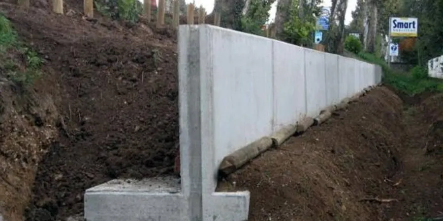
Cantilever Retaining Wall Design
Reinforced concrete L-walls and T-walls for retained heights up to 4.5 m, designed to Eurocode 2 and 7 with full stability checks, reinforcement detailing, and construction sequencing notes.
Sheet-Pile Wall Analysis
Embedded wall design using limit equilibrium and Winkler-spring methods for soft-ground sites in Hilsea and Tipner, including anchor force calculation and seepage analysis.
Gravity & Masonry Wall Assessment
Condition surveys and stability re-assessment of existing stone and brick retaining walls common in older Portsmouth terraces, with repair specifications where required.
Drainage & Waterproofing Detailing
Design of sub-surface drainage networks behind retaining walls including fin drains, carrier pipes, and sump connections, tailored to Portsmouth’s high water table.
Typical parameters
Quick answers
How much does retaining wall design cost for a typical Portsmouth project?
Design fees for a Portsmouth retaining wall typically range from £760 to £3,110 depending on wall type, retained height, and whether ground investigation data already exists. A straightforward cantilever wall under 2 m with existing borehole logs sits at the lower end; an embedded sheet-pile wall with surcharge from an adjacent building and a full interpretative report moves toward the upper end.
Do I need planning permission for a retaining wall in Portsmouth?
Under permitted development rules, a retaining wall under 1 m high adjacent to a highway or 2 m elsewhere generally does not require planning permission, but Portsmouth City Council may require Building Regulations approval under Part A (Structure). Walls over these heights, or in conservation areas like Old Portsmouth, often need full planning consent—our design package includes the structural calculations and drawings that Building Control will request.
How do you handle the high water table near Portsmouth Harbour?
We design the wall for hydrostatic pressure assuming a water table at 1.0–1.5 m below ground level, which is typical for harbour-adjacent sites. The drainage system includes a granular backfill column at least 300 mm wide against the wall, a perforated carrier pipe at the base, and weep holes at two levels. For basement retaining walls, we add a cavity drain membrane as a secondary line of defence.